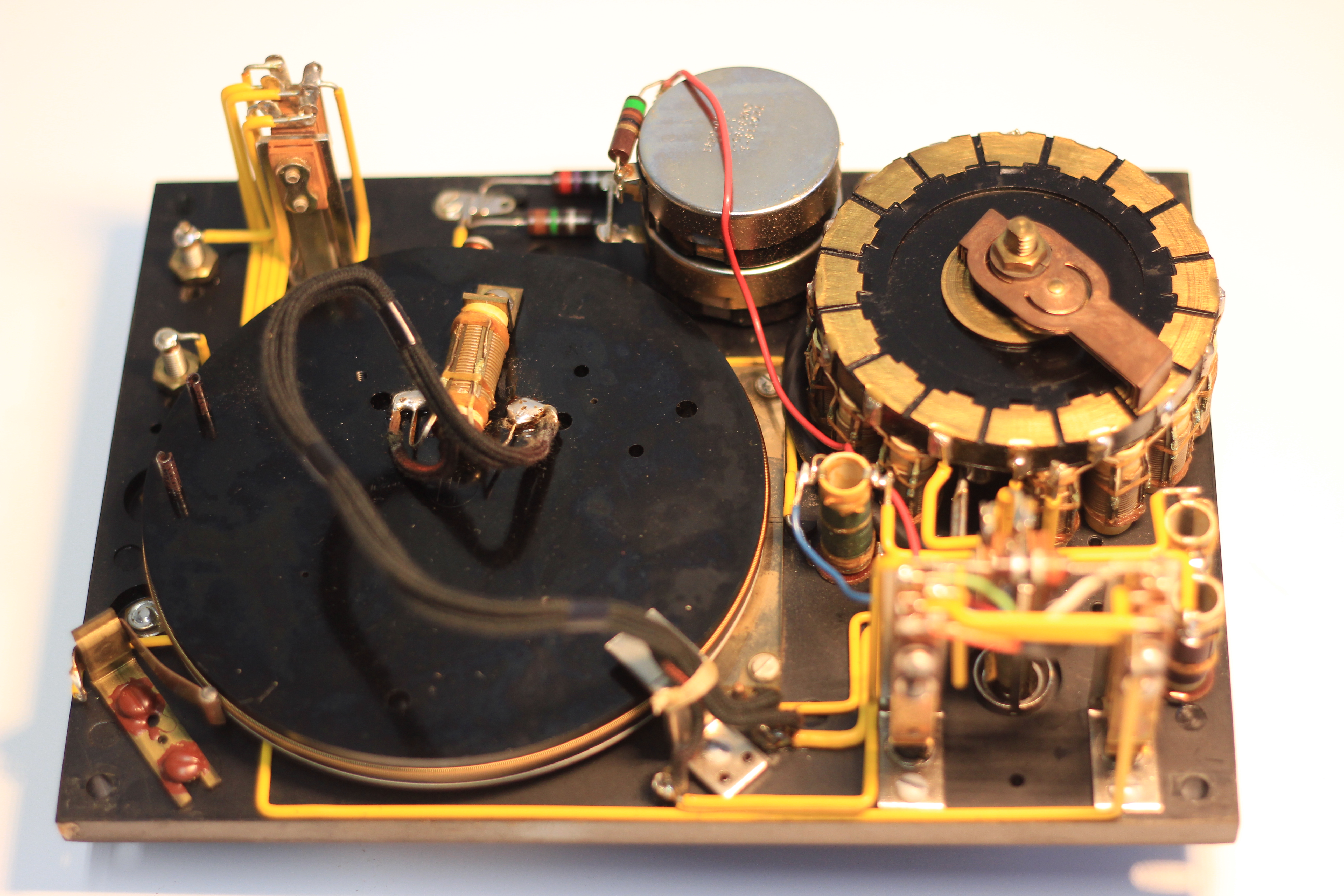
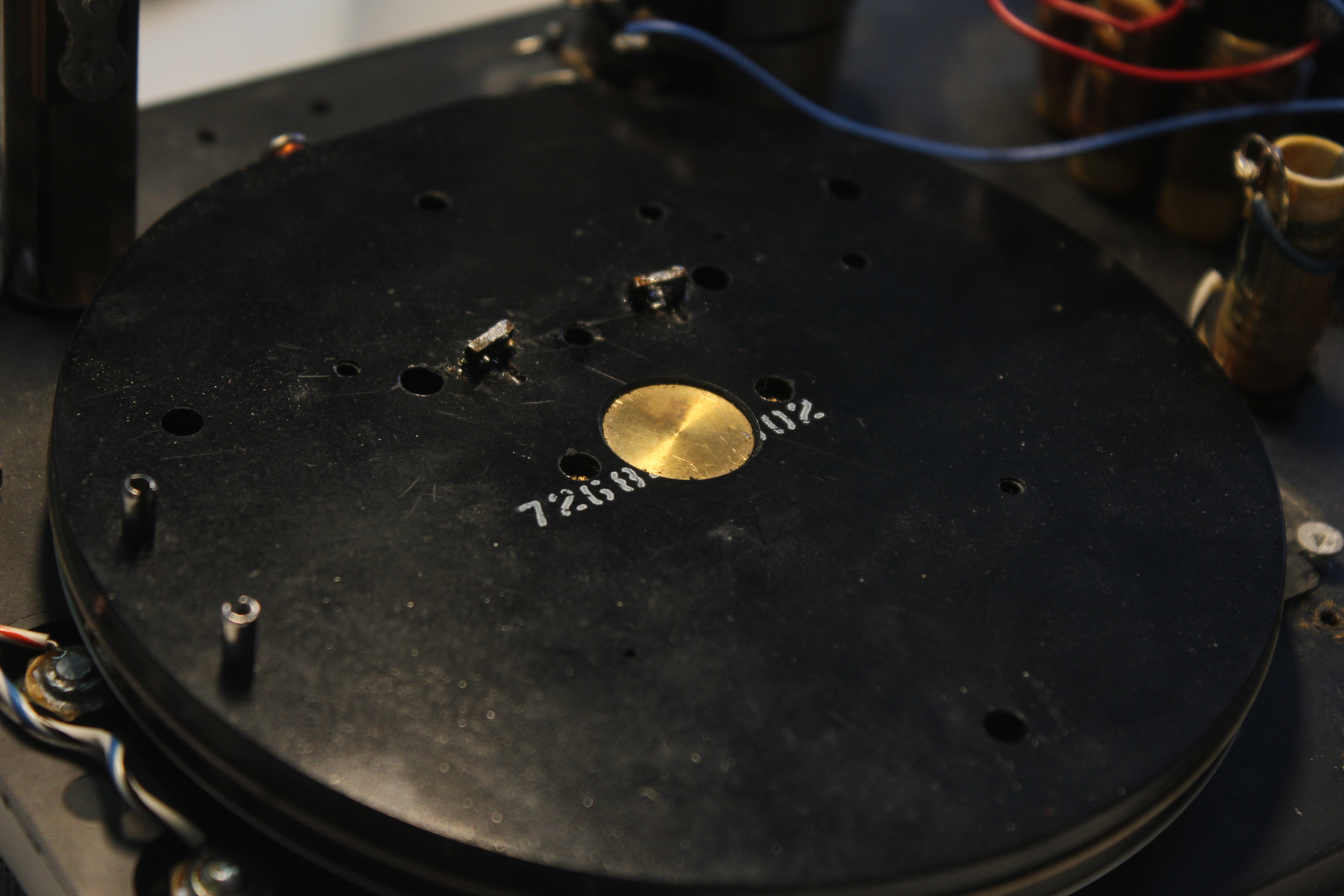
The main dial (that big black wheel on the left) is a huge wire-wound 1Ω potentiometer, and it’s busted. So I have to figure out the right kind of sensor and a way to mount it on the center axis of the wheel such that I can read the full range of motion it allows. Typical pots have their range of motion limited to an arc that is less than that allowed by the stops built into the wheel (the stops are the two posts sticking out of the wheel on the left side just above 9 o’clock).
Most potentiometers have around 270° of travel between the stops and that’s not enough. I thought about using a magnetic rotation sensor or an absolute encoder but those seemed way too complex for this.
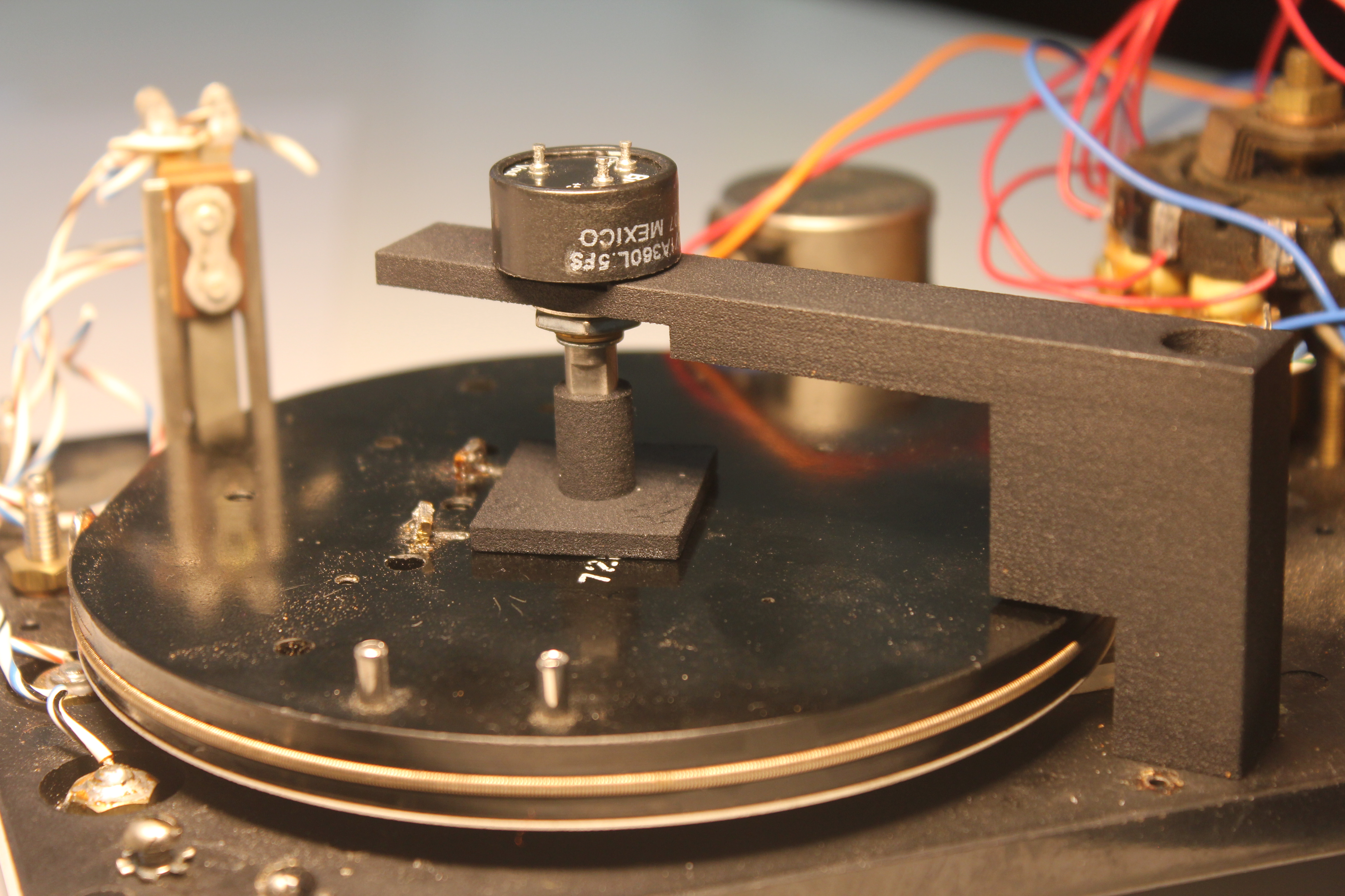
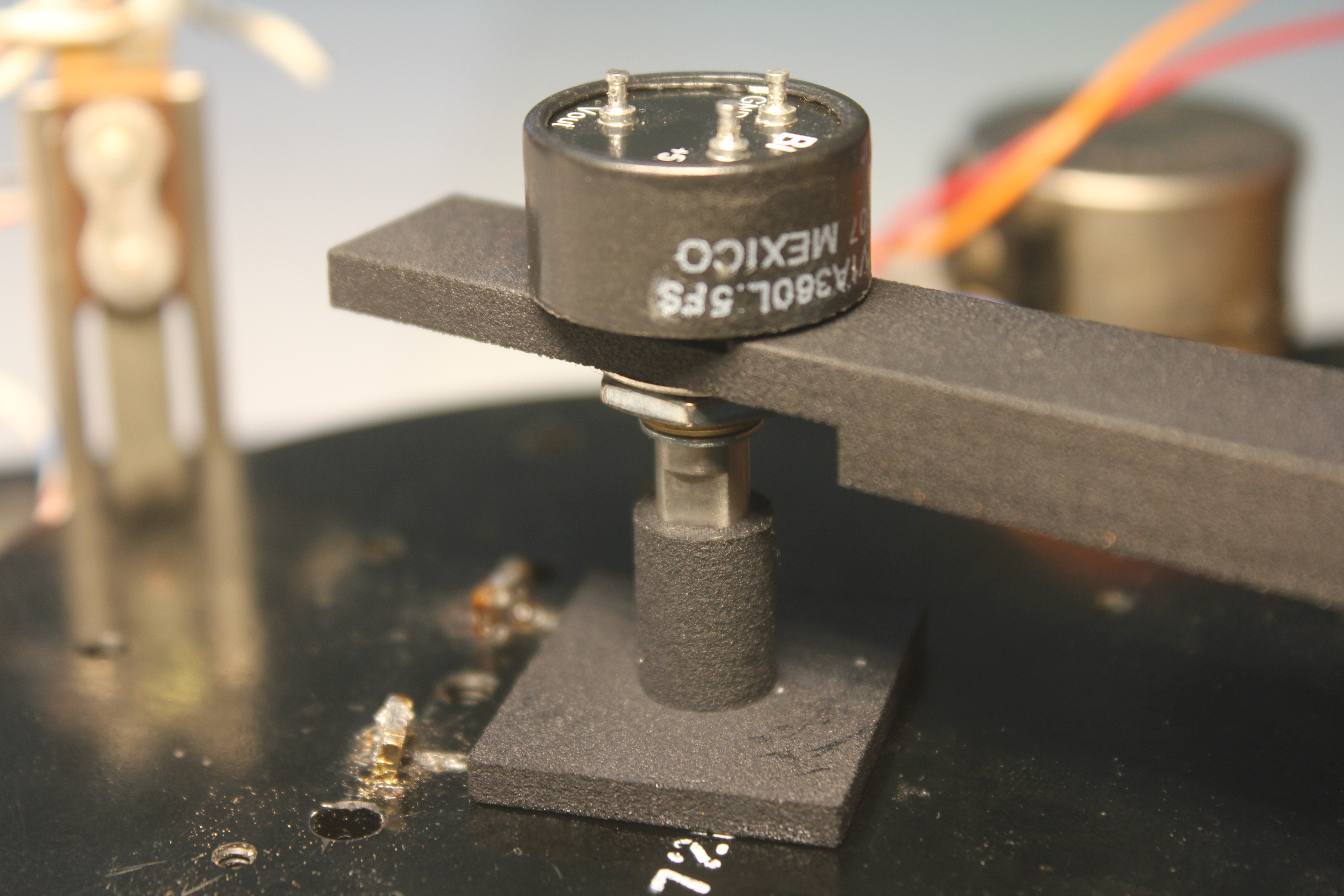
I settled on a TT Electronics Hall effect position sensor. It has no internal stops and emits a linear voltage proportional to the shaft position and seems to work perfect for what I need.
The next step was to design a bracket and socket to hold the body of the pot above the wheel, and a socket that mounts onto the wheel itself and accepts the potentiometer shaft. Thus began my first adventures in 3D printing!
I started out by roughly measuring the wheel and using Fusion 360 I built a rough 3D solid model. My measurement tools were only a metal ruler, an old divider that I still have from drafting class way back in the day, and a digital caliper.
The wheel has a shallow center hole, and two smaller holes along a line thru the center that I wanted to use as holes for the socket.
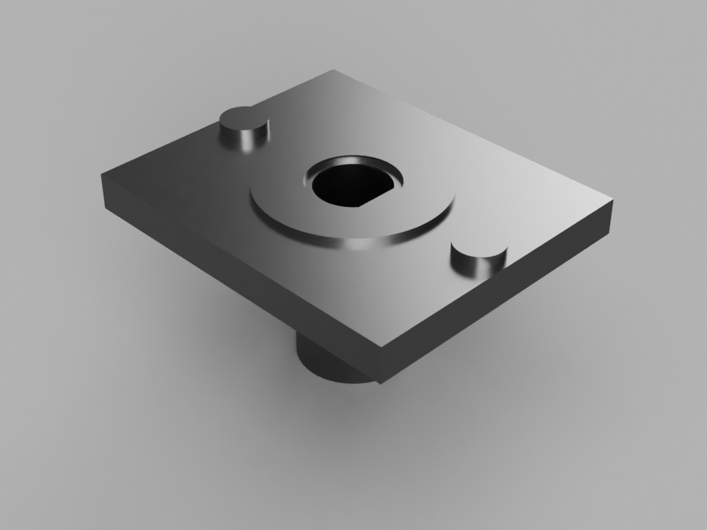
I measured the size and placement of these holes as best I could then built up the socket from there, creating a base below which two studs protruded to fit into the side holes, and above which protrudes a tube with an internal shaft detent. I transferred my measurements into Fusion and then hacked my way into a first version of my socket!
I have friends that tell me Shapeways is pretty cool and had read that Selective Laser Sintering (SLS) was the most dimensionally accurate printing method so I uploaded my socket and had it printed using SLS in white nylon. Much to my surprise, the first print actually fit both the wheel and the potentiometer shaft! However I got some things wrong when I went to build the bracket and threw the first socket away before I could snap a photo :(.
Next I had to build a model for the bracket that would hold the body of potentiometer. In the wheel photo you can see a silver metal object in the center on the lower side of the wheel. This blocks the two stopping pins and I figured was the right place to mount the bracket. I removed the stop and took some measurements then kinda estimated the reach of height that would be necessary to get to the center. I thought that I would just drill holes and machine the resulting 3D print rather than struggle right now trying to get it perfect so the first version of the bracket did not actually have a hole to mount the pot.
When I got the bracket back I tried to mount it and then crudely mark a center point above the wheel, then used a dremel to try and mill an elliptical hole. This kinda worked but the nylon material used in SLS really doesn’t like to be milled and left me with a bunch of melted flash around the hole that I had to slice off and sand. This first experiment did prove the concept but I realized that my first version did not include any material to act as a stop, and needed to be a bit wider, with the hole made during printing. Back in Fusion I made these mods and iterated through a couple of versions before I got where I needed to be. I trashed all of these prints before taking photos too .. phooey!
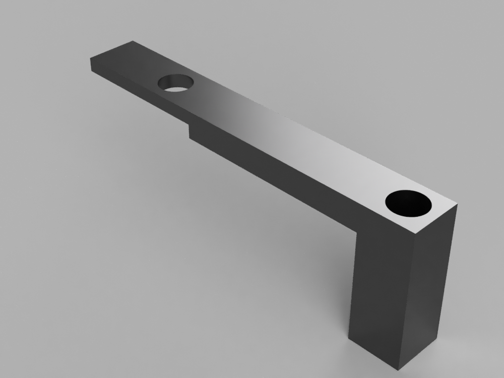
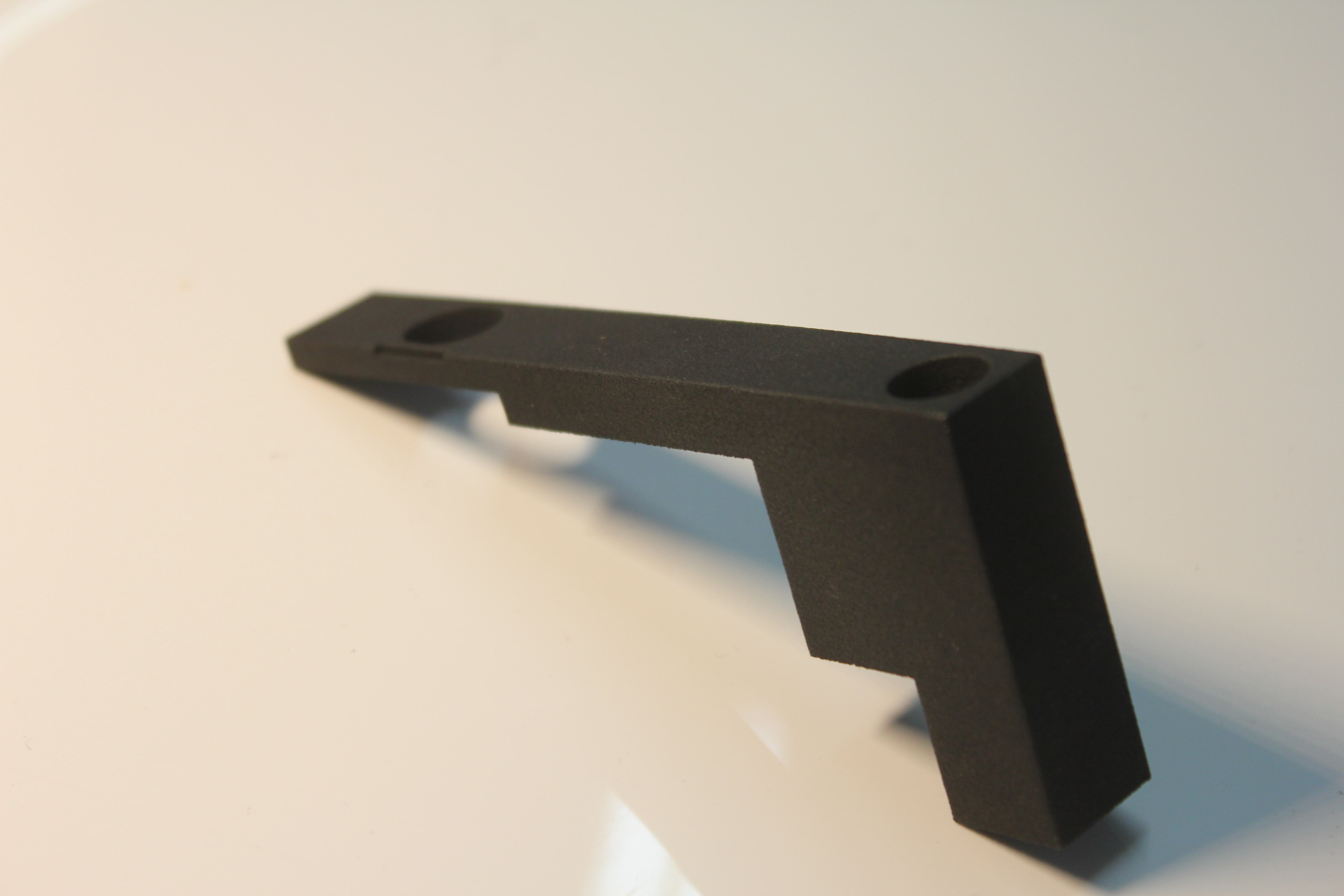
In the end I came up with this shape
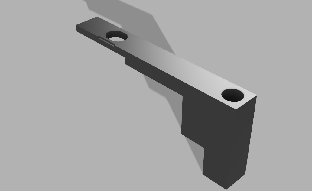
and the final printed article
Integration was pretty straightforward. I used some CA glue to fasten the socket to the main wheel and using a screw fastener from the original wheel stop I mounted the bracket with the attached sensor. It almost looks like it was part of the original engineering :)!